- #Modbus server and device not communication serial#
- #Modbus server and device not communication drivers#
- #Modbus server and device not communication driver#
- #Modbus server and device not communication manual#
For example, temperature readings should be linked to a reading block. The Modbus master can only read from a Reading block but can read and write from a Writing block. This is done using Crimson 2.0 Data Blocks.īlocks are given a direction, MC to Device (Reading) or Device to MC (Writing). In order to exchange data with the Modbus master, the Modular Controller has to make data available in Modbus register addresses. If these settings are changed, they will have to match the G3 settings set up later. Port settings can be adjusted to achieve faster communication (higher Baud Rate). In this example, the name is changed to G3, see Figure.

The device can be renamed for simpler usage. This device represents the Modbus Master device, in our case, the G3.

Click OK.Ī device called PLC1 now appears under the communication Port. Select Modbus under manufacturer and RTU Slave under Driver, refer to Figure 4.
#Modbus server and device not communication driver#
This will open the driver picker popup window. Select the RS232 Port and click the Edit button under the Driver Selection. The Modular Controller has to be set up as a Modbus Slave since the G3 will be the master. This example will use RS232 as a transport but it can be duplicated on any transports as long as the cable used and the driver associated are correct as shown in Figure 1. Once the modules are set up, double-click the Master to close this section and open the Communications area. For a temperature of 35.6 F, the register value will be 356. NOTE: This format does NOT influence Modbus as the Modular Controller transfers whole numbers (integers) and the decimal point is just a “dummy” point inserted on the display. For example, if the CSPID input is a thermocouple, the format will include one digit after the decimal point (000.0) where a process input might include two digits after the decimal point (000.00). It will not influence data availability on the communication but only data formats when creating tags in the G3. The module(s) can be programmed now or later. This step is required before the communication setup as data available for Modbus depends on the modules inserted.įor this example, a CSPID2 and CSTC8 module are inserted, see Figure 3. In Crimson 2.0, click on File>New and select Modular Controller for the Product Family and CSMSTRV2 for the Model, see Figure 2.Įnter in the area named Modules to insert the Modular Controller modules that fit the application. The first step is to create a Modular Controller database. Slave (Modular Controller) Setup Creating a Modular Controller Database
#Modbus server and device not communication drivers#
Crimson 2.0 will only provide the drivers related to the transport during setup, thus avoiding errors.įigure 1 shows the 3 different transports available and the drivers to be selected in each case.
#Modbus server and device not communication serial#
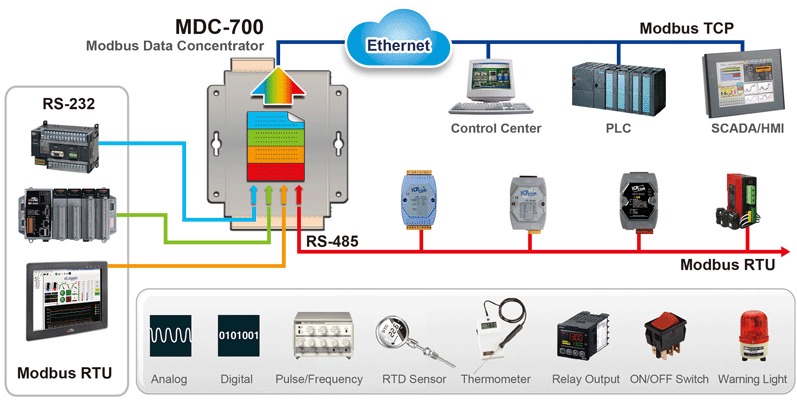
The following set up can be duplicated on any transports mentioned above with the only difference being the driver between serial and TCP/IP. The latest has it’s own protocol called Modbus TCP/IP. Multiple transports are supported by Modbus: RS232, RS485 or TCP/IP. The G3 will be the master in this example. Modbus is a single master multiple slave protocol. This also provides compatibility with other products supporting Modbus that could eventually be attached to the same bus.

Many PLC programmers or users know the basics of this protocol and its flexibility and ease of use makes it the perfect communication tool to exchange data between Red Lion Products. Modbus protocol is widely used in the industry and has become a standard for device-to-deviceĬommunication. This document shows instructions for Crimson 2.0, but the same steps are followed in Crimson 3.0 and 3.1.
#Modbus server and device not communication manual#
Please refer to the Modular Controller manual for module setup and parameter purpose. The following description will not go through the Modular Controller modules set up and will assume knowledge of each modules parameters from the user.

A technical note regarding the OPC set up can be found on Red Lion website here: This setup can be duplicated between any of the products listed above, although using OPC communication would be a better option in these cases that do not involve the CSMSTRV2. This document provides an introduction to connect a G3 HMI to a Modular Controller CSMSTRV2 using Modbus Serial Communication. Graphite HMI, Modular Controller, and PTV Use Case ProductsĬR1000 HMI, CR3000 HMI, DSP, G3 HMI, G3 Kadet HMI, Graphite Controller, This document provides an introduction to connecting two Crimson-programmed Red Lion devices via Modbus. Operator Interface Tech Note 32 - TNOI32 Abstract


 0 kommentar(er)
